Orange Pi Zero GPIO Pins

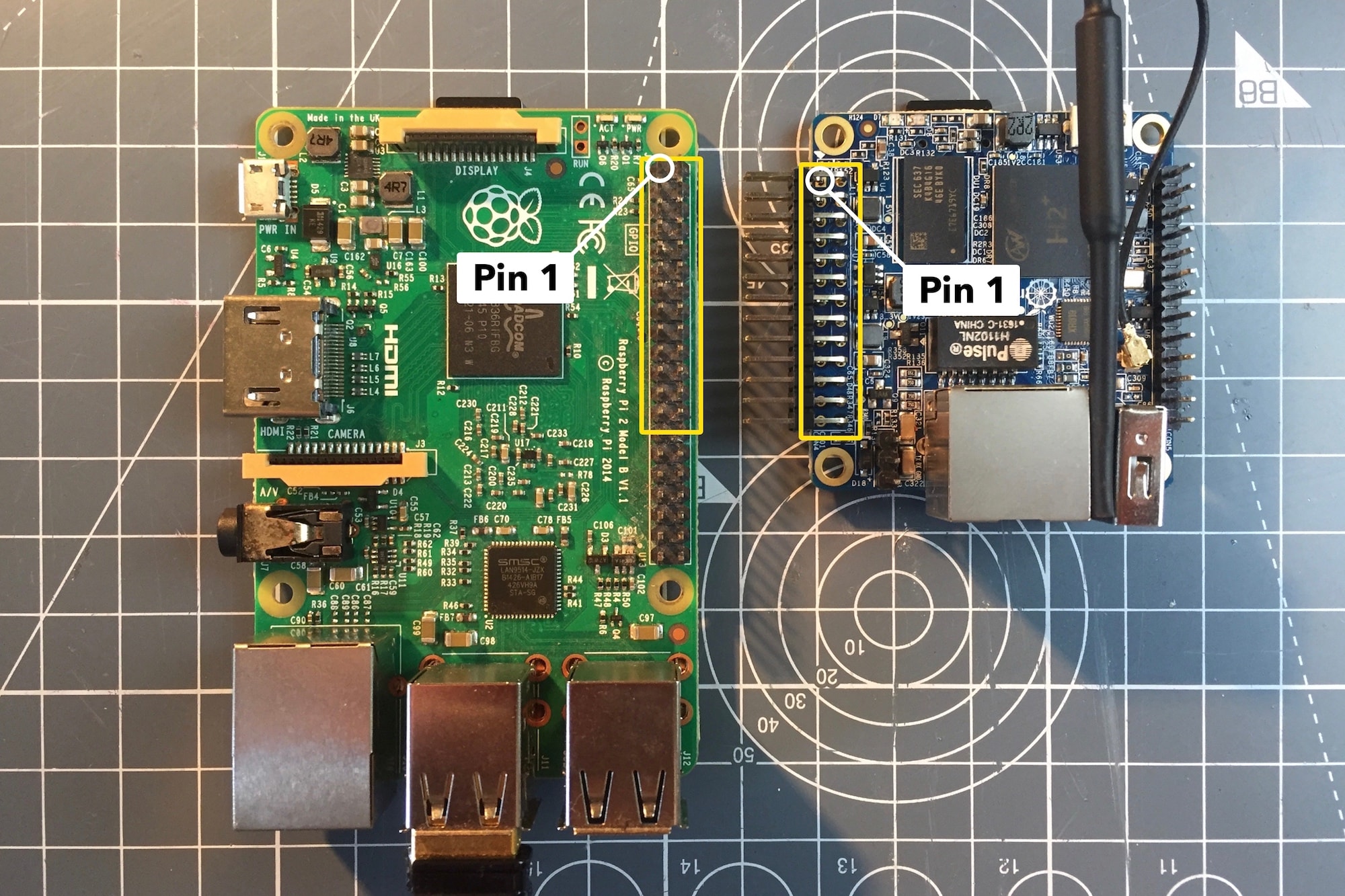
The 26-pin expansion port of the Orange Pi Zero is placed on the opposite side of the board compared to Raspberry Pi while the pinout is exactly the same:

Orange Pi Zero Expansion Board Location vs Raspberry Pi

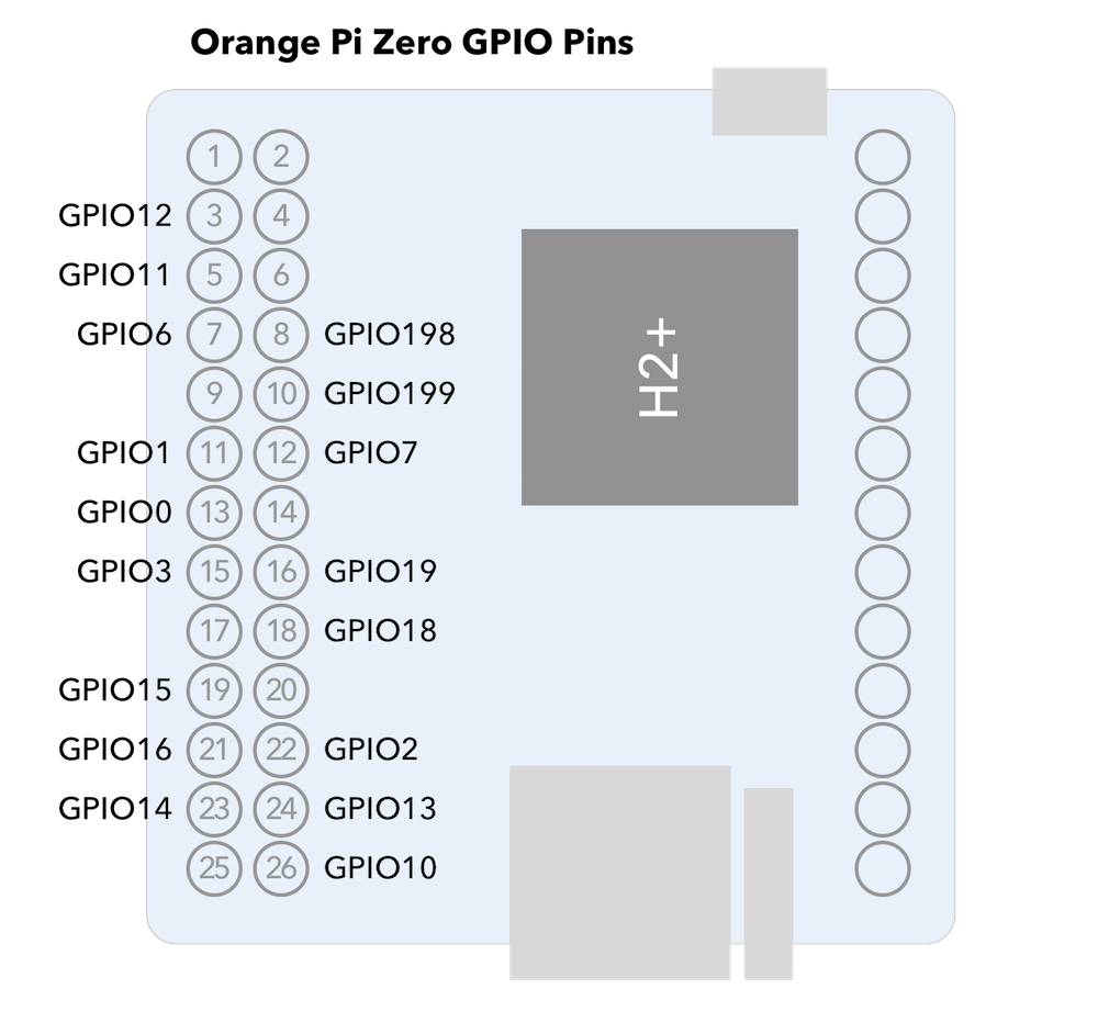
OSH Lab created a nice illustration of the Orange Pi Zero expansion port.

Orange Pi Zero GPIO Pins

It took me a while to discover that the General Purpose Input/Output (GPIO) numbering on the Orange Pi Zero with Armbian Legacy 3.4.113 is different from the Raspberry Pi and Raspbian. Here is how Allwinner SoC port names (such as PB12) are mapped to their GPIO pin numbers in the Linux kernel:

(Position of letter in alphabet - 1) * 32 + Pin number

For example, port PB12 would map to GPIO 44:

(2 - 1) * 32 + 12 = 44

Here is an online tool that does the GPIO mapping which I used when creating this illustration of the Orange Pi Zero GPIO pins:

Orange Pi Zero GPIO Pins

Orange Pi Zero GPIO Pins.

Using the GPIOs

Knowing the GPIO pin numbers is important for building all the Raspberry Pi based projects since their GPIOs are numbered differently (not sure how they do it, probably map to the datasheet?). In the follow-up post I show how to add an LCD monitor to the Orange Pi Zero via the SPI bus.

8 Comments

  1. Mark Birss says:

    Very nice, thank you for sharing

  2. fabien says:

    I had a hard time using my gpio’s on my orange pi zero.
    I use the functionality to control a little fan
    http://www.d0wn.com/control-the-orange-pi-zero-gpio/

  3. Mushfiq says:

    For which OS it can obtain maximum GPIO speed

  4. Sergio says:

    With a C program (header wiringPi.h) I have tested the pin cross reference. I found out a different association. In particular:

    3, 5, 7, 8, 10, 11, 12, 13, 15, 16, 18, 22, 23, 24, 26 // physical pins
    8, 9, 7, 28, 29, 0, 21, 2, 3, 30, 31, 6, 16, 15, 24 // wiringPi pins

    I could not find the cross reference of physical 19 and 21.

    Have you find it?

    • Kaspars says:

      Did you try running gpio readall? That should print out the full list of pin association.

      I just did a fresh clone and build of the original the wiringPi source which reports the following on an Orange Pi Zero:

       +-----+-----+---------+------+---+-Model  A-+---+------+---------+-----+-----+
       | BCM | wPi |   Name  | Mode | V | Physical | V | Mode | Name    | wPi | BCM |
       +-----+-----+---------+------+---+----++----+---+------+---------+-----+-----+
       |     |     |    3.3v |      |   |  1 || 2  |   |      | 5v      |     |     |
       |   2 |   8 |   SDA.1 |   IN | 0 |  3 || 4  |   |      | 5v      |     |     |
       |   3 |   9 |   SCL.1 |   IN | 0 |  5 || 6  |   |      | 0v      |     |     |
       |   4 |   7 | GPIO. 7 |   IN | 0 |  7 || 8  | 0 | IN   | TxD     | 15  | 14  |
       |     |     |      0v |      |   |  9 || 10 | 0 | IN   | RxD     | 16  | 15  |
       |  17 |   0 | GPIO. 0 |   IN | 0 | 11 || 12 | 0 | IN   | GPIO. 1 | 1   | 18  |
       |  27 |   2 | GPIO. 2 |   IN | 0 | 13 || 14 |   |      | 0v      |     |     |
       |  22 |   3 | GPIO. 3 |   IN | 0 | 15 || 16 | 0 | IN   | GPIO. 4 | 4   | 23  |
       |     |     |    3.3v |      |   | 17 || 18 | 0 | IN   | GPIO. 5 | 5   | 24  |
       |  10 |  12 |    MOSI |   IN | 0 | 19 || 20 |   |      | 0v      |     |     |
       |   9 |  13 |    MISO |   IN | 0 | 21 || 22 | 0 | IN   | GPIO. 6 | 6   | 25  |
       |  11 |  14 |    SCLK |   IN | 0 | 23 || 24 | 0 | IN   | CE0     | 10  | 8   |
       |     |     |      0v |      |   | 25 || 26 | 0 | IN   | CE1     | 11  | 7   |
       +-----+-----+---------+------+---+----++----+---+------+---------+-----+-----+
       | BCM | wPi |   Name  | Mode | V | Physical | V | Mode | Name    | wPi | BCM |
       +-----+-----+---------+------+---+-Model  A-+---+------+---------+-----+-----+

      I also did a fresh build of the WiringPi clone for Orange Pi Zero and it reports the following:

       +-----+-----+----------+------+---+-Orange Pi+---+---+------+---------+-----+--+
       | BCM | wPi |   Name   | Mode | V | Physical | V | Mode | Name     | wPi | BCM |
       +-----+-----+----------+------+---+----++----+---+------+----------+-----+-----+
       |     |     |     3.3v |      |   |  1 || 2  |   |      | 5v       |     |     |
       |  12 |   8 |    SDA.0 | ALT5 | 0 |  3 || 4  |   |      | 5V       |     |     |
       |  11 |   9 |    SCL.0 | ALT5 | 0 |  5 || 6  |   |      | 0v       |     |     |
       |   6 |   7 |   GPIO.7 | ALT3 | 0 |  7 || 8  | 0 | ALT3 | TxD3     | 15  | 13  |
       |     |     |       0v |      |   |  9 || 10 | 0 | ALT3 | RxD3     | 16  | 14  |
       |   1 |   0 |     RxD2 | ALT5 | 0 | 11 || 12 | 0 | ALT3 | GPIO.1   | 1   | 110 |
       |   0 |   2 |     TxD2 | ALT5 | 0 | 13 || 14 |   |      | 0v       |     |     |
       |   3 |   3 |     CTS2 | ALT3 | 0 | 15 || 16 | 0 | ALT3 | GPIO.4   | 4   | 68  |
       |     |     |     3.3v |      |   | 17 || 18 | 0 | ALT3 | GPIO.5   | 5   | 71  |
       |  64 |  12 |     MOSI | ALT4 | 0 | 19 || 20 |   |      | 0v       |     |     |
       |  65 |  13 |     MISO | ALT4 | 0 | 21 || 22 | 0 | ALT3 | RTS2     | 6   | 2   |
       |  66 |  14 |     SCLK | ALT4 | 0 | 23 || 24 | 0 | ALT4 | CE0      | 10  | 67  |
       |     |     |       0v |      |   | 25 || 26 | 0 | ALT3 | GPIO.11  | 11  | 21  |
       |  19 |  30 |    SDA.1 | ALT4 | 0 | 27 || 28 | 0 | ALT4 | SCL.1    | 31  | 18  |
       |   7 |  21 |  GPIO.21 | ALT3 | 0 | 29 || 30 |   |      | 0v       |     |     |
       |   8 |  22 |  GPIO.22 | ALT3 | 0 | 31 || 32 | 0 | ALT3 | RTS1     | 26  | 200 |
       |   9 |  23 |  GPIO.23 | ALT3 | 0 | 33 || 34 |   |      | 0v       |     |     |
       |  10 |  24 |  GPIO.24 |  OUT | 1 | 35 || 36 | 0 | ALT3 | CTS1     | 27  | 201 |
       |  20 |  25 |  GPIO.25 |  OUT | 1 | 37 || 38 | 0 | ALT5 | TxD1     | 28  | 198 |
       |     |     |       0v |      |   | 39 || 40 | 0 | ALT5 | RxD1     | 29  | 199 |
       +-----+-----+----------+------+---+----++----+---+------+----------+-----+-----+
       | BCM | wPi |   Name   | Mode | V | Physical | V | Mode | Name     | wPi | BCM |
       +-----+-----+----------+------+---+-Orange Pi+---+------+----------+-----+-----+

      Note that in both cases pins 19 and 21 are mapped to MOSI and MISO.

  5. Sergio says:

    yes I used the cmd “gpio readall”. The output is like yours. But based on C program the two pins configured as input (pulled down) do not react to
    digitalWrite (j, HIGH)
    with 0<j<203
    I'm wondering what could be the reason.

Leave a Reply