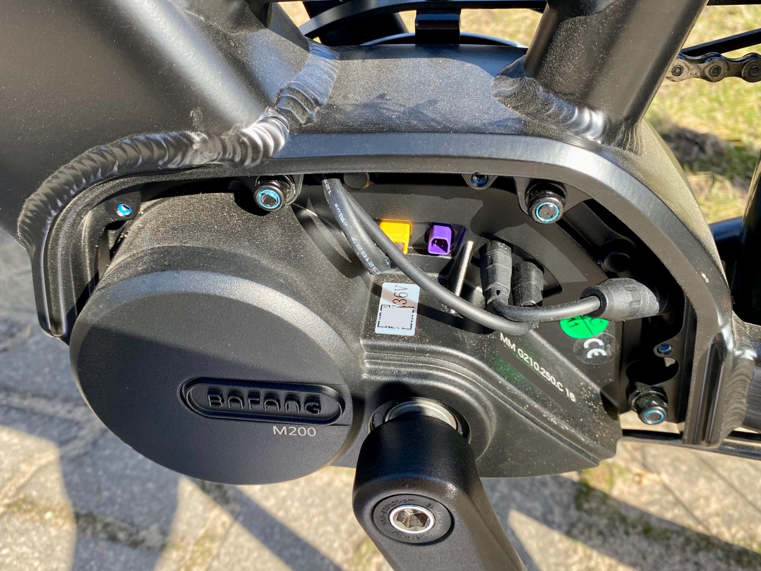
MM G210.250.C) with 36V battery connector (yellow, from left), empty 6-pin electric break connector (purple), 8-pin rear light and wheel speed connector, and 8-pin front light and display connector.I got my wife this Accolmile Antelope 1S electric bicycle with Bafang components from their latest M-series lineup of mid-drive motors and displays which communicate over a CAN bus. It’s a great city bike and the price includes fast shipping from the warehouse in Poland. Their support was also quick to send a replacement wheel for the original that got dented during transport (despite the thoughtful packaging).
CAN over NodeJS
The M500/M600 motors are particularly popular with MTB riders so the communication protocol has been discussed in this forum thread and documented in this GitHub repository. Importantly, the BESST software for managing the configuration and firmware updates is an Electron app with all logic as plain HTML and JS files (and bundled source maps for all minified code), including the CAN frame specification. I’ve started documenting my research in this GitHub repository.
Connecting to CAN Bus

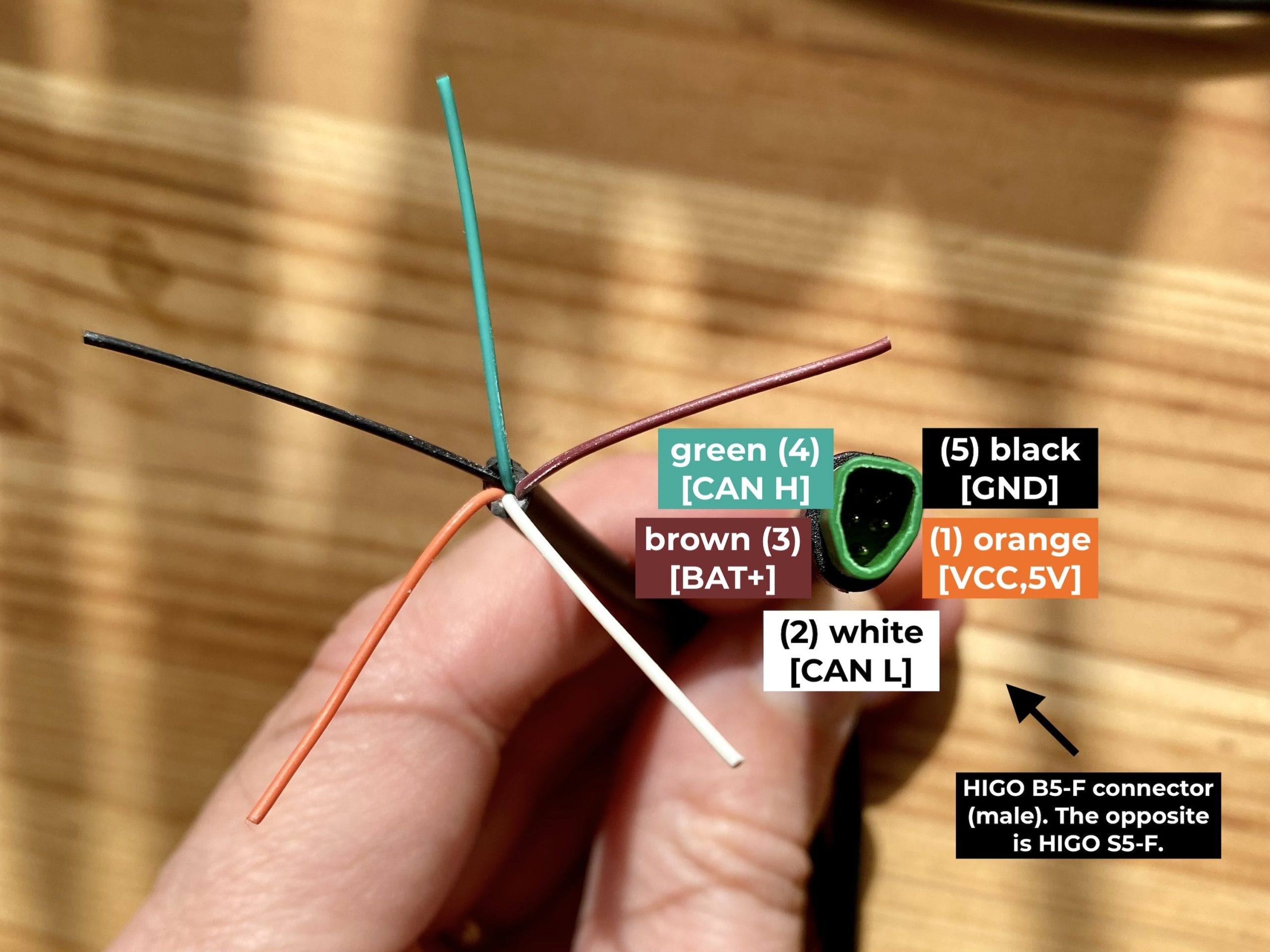
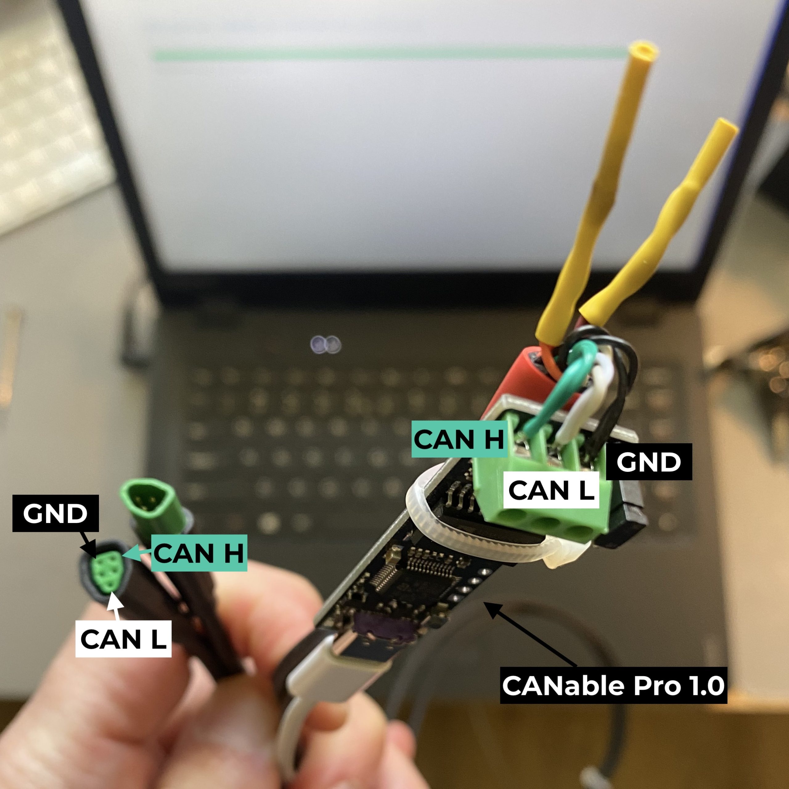
The display connector at the wheel is the most convenient place to tap into the CAN bus. I purchased two HIGO 5-pin connectors B5-F and S5-F from ETShop in Germany for around €7 each (AliExpress / Amazon) and soldered the CAN high (green), CAN low (white) and ground (black) wires from each for a connection to (a copy of) the CANable Pro 1.0 CAN-to-USB adapter (AliExpress / Amazon). Be sure to test the wiring with a multimeter because one of the wires carries the full battery voltage!
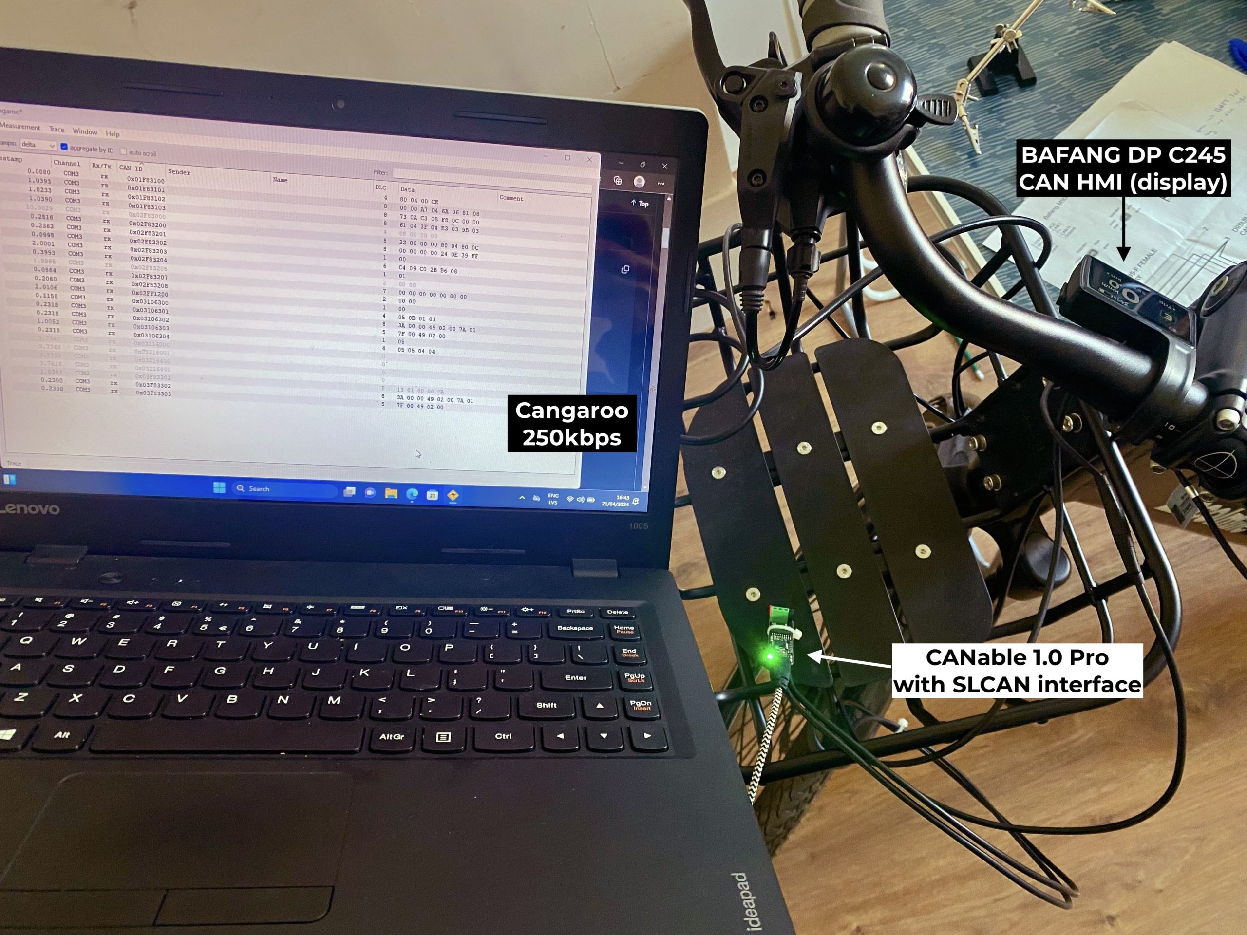
Technically any CAN-to-USB adapter will work (as long as it supports 250kbit transfer rate) and the choice depends more on the software you want to use for interacting with the bus. The CANable adapter runs the slcan firmware which implements the Lawicel SLCAN protocol (a basic ASCII serial) which is supported by various libraries, including SocketCAN.
Update Controller Configuration Manually
I was able to test the setup by increasing the assisted maximum speed to 60km/h from the original 25km/h by sending a CAN message composed of the following components:
0x05for the message source (0x01— torque sensor,0x02— controller,0x03— display or HMI,0x04— battery,0x05— BESST),0x02for the message target (controller),0x00for a WRITE operation (0x01for READ),
which are transformed into a frame ID prefix for the 0x3203 code and subcode for “speed limit, wheel diameter and circumference” registry through this transformer function:
buildHexStringCommand = (source, target, opt, anfn, nfn) => {
    const cmdPrefix = hexAllocToBinaryStr(source.toString(16), 5) + hexAllocToBinaryStr(target.toString(16), 5) + hexAllocToBinaryStr(opt.toString(16), 3);
    let cmdPrefixHex = parseInt(cmdPrefix, 2).toString(16);
    if (cmdPrefixHex.length % 2 !== 0) {
        cmdPrefixHex = '0' + cmdPrefixHex;
    }
    let cmdHexString = cmdPrefixHex + anfn + nfn;
    return hexReverse(cmdHexString);
};
which returns:
05 10 32 03as the frame ID along with the payload:
70 17 C0 2B B6 08 where (with little-endian byte order):
0x1770is 6000 or 60km/h × 100,0x2BC0is 700 or 700c wheel diameter (29-inch), and0x08B6is 2230 or 2230mm wheel circumference.
Use Bafang CANable Pro Software
There is now the Bafang CANable Pro open-source software that allows you to configure all parameters using a desktop app (see related forum thread). Importantly, this requires CANable to be running the candlelight firmware since it uses the GS_USB protocol for talking directly to the USB device without the Serial/UART translation layer.
Hello. Maybe you will be interested in my project https://github.com/andrey-pr/OpenBafangTool . Its desktop configuration (and diagnostic) software for bafangs with can, and its already usable
Thank you for the description: I found it clearer than elsewhere. I’m quite familiar with CAN, so all I needed is a description what message to send, and what is the wiring.
To help others who find this article, I’ll add a few stumbling points that are not mentioned:
05 10 32 03. But since you provide the contents description, it is crucial to note the length of each field:All this is, of course, just a Bafang’s invention: the CAN standard does not prescribe interpretation of the ID or data.
The content is exactly 6 bytes long (generally it can be variable 0 to 8 and has to be set explicitly).
I couldn’t work out the units for the wheel diameter (even though it’s probably only used for display). In any case, if we only want to change the speed limit, we’d better keep the existing values for the lower 4 bytes. To get them, we could probably request this message by changing the operation to READ, but there is no need to: the controller periodically sends this data anyway. We just need to run our favourite CAN software and intercept all messages for a few seconds while power is on. Then look for a message with the same 3203 code in the lower part of ID (mine was
02F83203), and copy the data from there, just replacing the first two bytes with the desired speed (low-endian in 0.01 km/h).Works a treat: just a single message to send, no handshakes, encryption or other higher-level stuff.
Very interesting to read.
I have a question. When buying a Canable (now 2.0), it’s best to use the isolated version like you did? I’ve a Tenways AGO-X bike with an M410 motor and want to give it a little bit more assisted speed around 30Km/h.
It wouldn’t hurt, that’s for sure! The risk of connecting the battery voltage to one of the data pins is definitely valid. I think the CAN transceiver chips have their own isolation but I’m not 100% sure.
I just connected my Canable 2.0 Pro with my bike (M410 motor) and when I connected the canable with the computer the HMI screen went out and now I’m unable to power on my bike. Have you any idea what could went wrong? I checked the wires at first to be sure and they are like on your pictures. Or is there a safety or something else?
I just measured and there is no power on the Black and Brown Wire, before when I measured I measured the battery voltage. So is there a safety or some sort of breaker.
Can you please share a diagram of the full wiring? The connection from the motor should go to the Canable (with CAN terminating resistor disabled) and then back to the screen. The screen should work even if you don’t connect Canable to the computer. Use the continuity mode on a multimeter to confirm that pins connecting to the motor are still connected to the matching HMI pins when the Canable is in place.
pod tym linkiem jest wyjaśnione jak działa załączanie sterownika przez wyświetlacz z can. Dołączone są schematy jak samemu sobie go zbudować.
https://opensourceebike.github.io/easy_diy_display_ebike_display/build_display-bafang_m500_M600.html
Very Very strange, when I first took out my battery and pushed the button to see how full the battery was (it’s one button and a LED with red and blue color modes) nothing happened but after I did that same thing again, the LED lighted up and showed me the battery is almost full so a blue light and when placing the battery back and trying to turn on the power with my HMI it worked again. Now I’m afraid to test things with my Canable :( (Sorry for spamming this topic, I’m full of adrenaline, it’s a brand new bike).
this happened to me for another reason, from the spark of the initial battery connection, it went in protective mode or something, and when the BMS capacitors forgot about it it worked again.
I made a picture of my Canable and how I have my wires connected, I also did a continuity test from both ends (male to female) of the wires and that was positive. I also did a continuity test between the female connector and the Wago/Canable and between the male connector and the Wago/Canable.
First I connected all the cables like in my picture (see here) without connecting the Canable to my laptop and after that I switched on my HMI display. The moment I connected the Canable to my laptop with it’s usb cable the HMI display went out and by unplugging the Canable from my laptop I was not able to power on my HMI display and when I measured there was no voltage between the Brown and Black wire and at the beginning when I started there was a battery voltage (I believe it was 36V or something, battery was at 70% when starting the experiment)
I have no idea if that is normal behavior but after that I was just unable to power on my bike and now I’m not really sure how or why it eventually worked again.
I’ve got my bike a few weeks now and I’m not so fond of trying it again. What I just found out is if you remove the existing HMI and replace it with a 600C HMI then you are also able to change the speed limit and that display gives more info while riding the bike. Maybe that’s a more secure way. Topic is here.
Do you have the pin out for BAFANG BE-Bus battery communication connector? I assume they are Can-H, Can-L and Gnd but cannot find the pin out documentation anywhere.
Unfortunately I don’t have that.
Hello, thank you for this post, maybe someone can help me with my configuration, i have connected my bafang with a usb-can-interface and was able to read the can-communication but i did non found the adresses or packets you wrote about.
(and i am not sure where the jumper on the interface is for, but without the jumper it does not work, i can’t read the communication, with the jumper it stops after several seconds and the DP C080.CB shuts down, when i start without the jumper and put it later in, then it works for a longer time)
The parts work great, but i am not abled to drive more than ~30 km/h
in the DP C080.CB i configured:
20 inch wheel size (which fits my wheels)
1580mm diameter
60 km/h
the speed shown while driving seems correct
the parts are:
MM G340 (750watt)
DP C080.CB
here is the can output: (I deleted the duplicate lines)
https://pastebin.com/YCS9fV5R
i connected the DP C080.CB with the bafang-go app, i’m not sure where the limitations comes from, the motor or the DP C080.CB ?
thanks in advance!
I believe the speed limit is set in the motor controller and the display only shows it and/or allows updating it.
Can you please elaborate on what you mean by “in the DP C080.CB i configured”? Does the display have the option to increase the speed limit to 60km/h? Did you press “+” and “-” at the same time to save the setting? Does it show the 60km/h limit in the display after restarting the bike?
I personally don’t have experience with the motor you mentioned. Have you tried using the OpenBafangTool mentioned in the earlier comments?
Thanks for posting this. In one of your replies you mentioned removing the termination resistor. Why would you do this? Isn’t CAN a broadcast bus and each end point needs to be terminated properly to remove reflections, get the proper voltage swing between CANL and CANH etc?
I’m planning on using the seeedstudio usb-can analyzer to observer what’s going on with my bafang hub motor
New to this bus and just trying to understand. – Thanks Mike
That’s a great question! My understanding is that the termination needs to happen at the physical ends of the bus. Since the monitoring device is added inline with the hand remote, it doesn’t need the termination.
Hey Kaspars
Thanks for all the information, I’m trying run the motor calibration with a Lawicel and SAVVYCan, was there anything special you had to do before sending the message? I’ve tried sending the 0x6200 messages without success
No, I didn’t have to do anything special. The important thing was to leave the display connected at all times as it appears to be exchanging some heartbeat data that keeps the connection alive and valid.